Case Study: Custom OLED Driver Board
Project Overview
During the hardware iteration for version 3 of the PocketMage PDA, the design required a 256×32 pixel OLED to double the horizontal screen space. Because this specific 8:1 aspect ratio panel (SSD1326) is a niche component, there were no off-the-shelf breakout boards available. I designed and manufactured a custom display driver board to test and validate the screen’s circuitry before integrating it into the main PocketMage PCB.
Hardware Architecture
The display required a 12V power supply, which conflicted with the 3.3V logic used by the core microcontroller. The custom board was designed to bridge this gap, focusing on two main subsystems:
- Power Regulation: Implemented a Texas Instruments boost converter to step up the 3.3V input to a stable 12V output. The component selection and PCB layout were derived directly from the manufacturer’s application notes to ensure proper power efficiency.
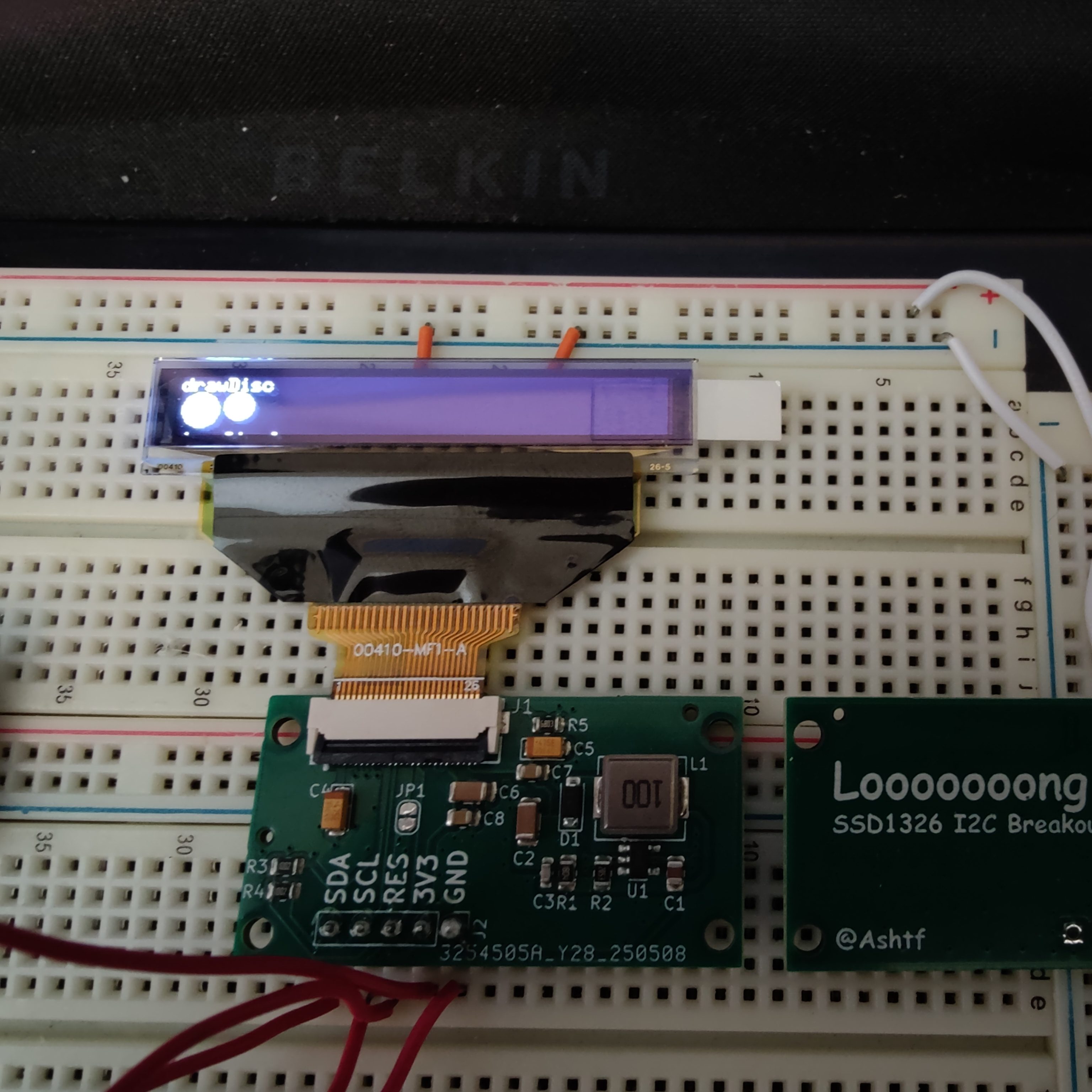
- Display Interface: Integrated a 26-pin FPC connector to interface with the OLED’s ribbon cable, removing the need for direct component soldering. The circuit includes required decoupling capacitors and 10k pull-up resistors on the SDA and SCL lines for standard I2C communication.
Prototyping and Bring-Up
The board was designed in KiCad and sent to a board house for rapid prototyping. Upon receiving the hardware, initial multimeter testing verified a stable 12.04V output from the boost converter, confirming it was safe to connect the display.
The breakout board was then interfaced with an ESP32 development module on a breadboard. Using the Arduino IDE and the U8g2 graphics library, I developed standard test firmware to validate I2C communication, screen rendering, and refresh rates. This short development sprint successfully de-risked the power delivery and display logic, allowing for direct implementation into the next main board revision.